Sandpaper Surface Roughness
The 3D topology of coarse sandpaper is notoriously difficult to measure. Figure 1 shows an optical image of commercial 80 grit sample manufactured with garnet grit and a red adhesive binder to hold the grains onto the “loop” (backing) of the paper. In some cases it is possible to image the surface of sandpaper with a stylus profilometer by stitching together a series of adjacent 2D line profiles into a composite 3D image. The image resolution along the scanning axis is generally good, while the resolution along the orthogonal axis is limited by the spacing employed between the scan lines. However, it should be recognized that the image produced by a profilometer is the convolution of the surface topology and the stylus tip shape, and as the sandpaper grains increase in size the convolution effect will produce an increasingly distort view of the surface topology. Also, a serious mechanical problem arises as the grain size increases. The stylus tip can become pinned in a tight crevasse between grains and actually be pulled out of its holder in the profiler tool.
The largest grain size which can be practically imaged via profilometery is 80 grit, as shown in Figure 2. For coarser grits it is essential to switch to an optical imaging technique. Figure 3 illustrates the large, jagged grain shapes typically found in 40 grit sandpaper. This very rough topology can be imaged accurately using the camera frame stacking, best-focus imaging technique, as shown in Figure 4.

Figure 1 Optical image of 80 grit sandpaper. FOV 1.4mm.

Figure 3 Darkfield microscope image of 40 grit sandpaper grains viewed at 45° with respect to the surface.

Figure 2 Stylus profiler image of 80 grit sandpaper. 100 scan lines.

Figure 4 40 grit sandpaper imaged using best-focus frame stacking and image stitching. 64 images; 120 frames per image.
Paint Layer Thickness
This isn’t an exciting metrology application, but it is a practical one. Whether a commercial production warranty has been violated depends, in part, upon determining if the paint was correctly applied to the surface. Three examples of paint thickness measurements are given below.
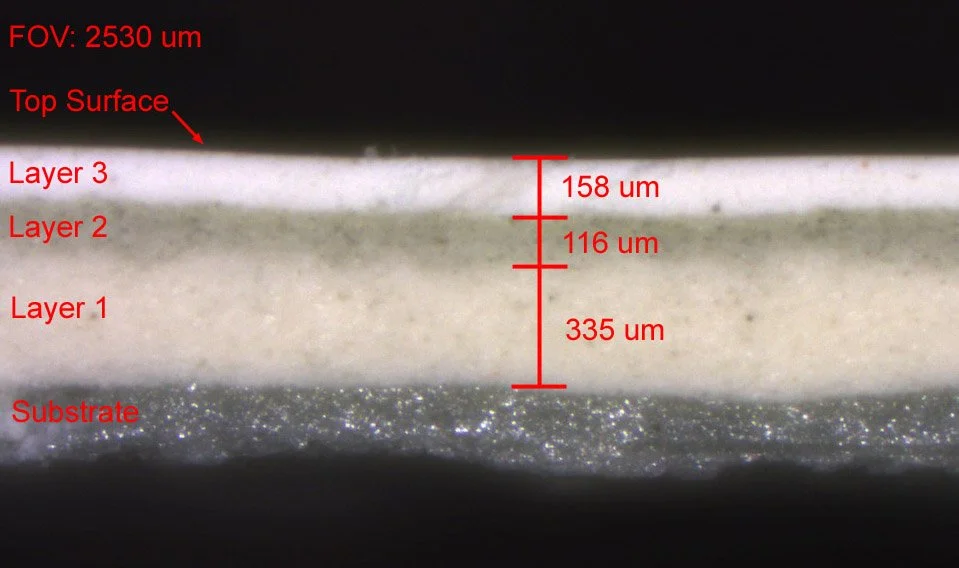
Figure 1

Figure 3

Figure 2
Abalone Respiratory Hole Dimensions
As abalone grow they form new, larger vent holes on the periphery of their shells, while older ones are eventually sealed shut. The camera frame stacking, best-focus imaging technique was applied to obtain the physical geometry of individual vent holes in the shell. The 3D topology and black-and-white top-view images shown in Figures 2,3 were obtained simultaneously in the imaging process. A 6x6 matrix of 36 sub-images were stitched together to produce the composite image, with the data from 150 camera frames used to generate each of the 36 sub-images.

Figure 1 Darkfield microscope image.

Figure 2 Best-focus B&W picture.

Figure 3 Vent hole 3D topology.
iPhone Connector Pin Failure
Pin 5 on both sides of the symmetrical Apple Lightning connector carries the positive power current for charging an Apple device. For the cable connector shown below this pin prematurely failed under normal use. The microscope view in Figure 1 makes the failure visually apparent, though the height of the surface features is not measured. The vertical scanning interferometry (VSI) image shown in Figure 2 gives detailed information about the 3D topology of the defective connector surface.

Figure 1 Darkfield microscope image of damaged iPhone connector pin 5.

Figure 2 VSI image of pin 5.